Page 1 of 2
Issues with I2C for PIC18F252 and GLK12232-25-SM
Posted: Mon Jun 11, 2007 3:49 pm
by YYS
Hi. My name is Yu-Chen. Some friends and I were trying to get the PIC18F252 to transmit data to the GLK12232-25-SM LCD via I2C. However, we are running into some trouble about the LCD not accepting input data.
The LCD is setup according to the changes indicated for PCB 1.4 of GLK12232-25-SM for the I2C, and connections have been checked to make sure that data is going through. A scope is also used to visually see actual bits being transmitted as well.
The code is written for the C18 compiler, using I2C commands predefined in its library. The code is main.c attached to this message. The data transmission command, putsI2C() (i2c_puts.c), is also included in the attachments. The codes are written with hardware peripheral functions, but there are also software peripheral functions. Those go under mainsoftware.c in the attachments. Mainsoftware.c is coded slightly different from main.c, but neither of them worked during testing.
For more information about C18 I2C commands, visit the following pdf and check on the pages listed below:
http://ww1.microchip.com/downloads/en/d ... 51297f.pdf
1. Hardware Peripheral Functions for I2C - Pg. 25-38
2. Software Peripheral Functions for I2C - Pg. 109-114
I was wondering if there were some problems in our coding that resulted in the LCD not accepting the commands we tried to input, and if anyone can post corrections that would be great.
Thanks.
Posted: Mon Jun 11, 2007 5:09 pm
by Raquel
Hello Yu-Chen,
Thanks for your post.
I looked at your code and it looks good. I suggest though, that before drawing lines, maybe you want try to clear the screen first ( 254 / 88 )? Also, a side note, if you wanted to draw lines on the screen, there is a command for that: 254 / 108 / <+ parameters>.
What I would like to see is for a scope capture. If you please post a scope capture so we can slearly see what is happening on the SCL and SDA lines, something like the following
post
Thanks,
Posted: Mon Jun 11, 2007 5:57 pm
by YYS
Hi Raquel.
I will get you the scope captures tomorrow (because I'm not the one doing it, and the equipments are not at my place either), but I can explain some weird things about them right now. For one of the lines (I think it was SDA line) the voltage seems to drop below 5V while the other one stays at 5V with no problem.
As for the start up screen, I think we uploaded an empty bitmap using MOGD Sharp so that nothing appears on the start up screen right now. Also, we wanted to test the draw pixel feature, not the draw lines feature (despite in this testing we drew a diagonal line). That's the main reason why we didn't use draw lines command.
Thanks again.
Yu-Chen Shih
Posted: Tue Jun 12, 2007 10:28 am
by YYS
Hi again.
I found something on the manual today that could be the problem. Under the I2C section, it says to input the following commands 254/160/0 to the LCD to turn off the auto transmission of data in RS232. I checked the commands list and didn't see this anywhere, and we can't apply this command using MOGD# either (since MOGD# doesn't support hand typed commands, but it would be nice to include that feature to apply some commands not featured in the software to the LCD). I was wondering if I can apply this code using I2C (or would I have to do it through RS232)?
One other question. Due to some weird reason, our baud rate for RS232 is messed up, and setting it in MOGD# is no good either. Right now, the only way to keep the baud rate set properly is through the reset pins. I know that I have to save the settings in order to get rid of this problem, but I looked at the command list in the manual and don't see a save settings command (only save contrast and etc.). If someone can post the command that would be great.
Thanks again.
Yu-Chen Shih
Posted: Tue Jun 12, 2007 10:47 am
by Raquel
Hello,
I am not sure what GLK12232-25-SM PCB you have. Do you have a Rev 2.0 or Rev 1.4?
Posted: Tue Jun 12, 2007 11:07 am
by YYS
Hi. We have Rev 1.4. I checked manual 1.4 and 2.0, but 254/160/0 command is not listed in either manual's command list. It is only mentioned by manual 2.0 in the I2C section on page 16.
Yu-Chen Shih
Posted: Tue Jun 12, 2007 11:18 am
by Raquel
Command 254 / 160 is only for GLK12232-25-SM PCB 2.0. Mogd# is also for PCB Rev 2.0 only.
Do you have a scope capture yet?
Posted: Tue Jun 12, 2007 12:07 pm
by YYS
Hi.
I see, we'll try MOGD and see if it fixes the baud rate issue. Although asides from that MOGD works fine in terms of bitamp uploading and text input testing.
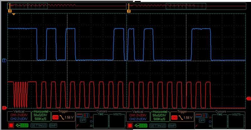
The scope capture is listed below. I hope it will be of help in solving the problem.
Thanks.
Yu-Chen Shih
Posted: Tue Jun 12, 2007 12:22 pm
by Raquel
Thanks for the capture.
I see that you are not getting ACK'ed although you are sending the right address. Can you please turn the power off, take off any keypad connected, and temporarily jump pins 6 and 7 of the keypad connector. Power the display back up and see if you get ACK'ed by the display.
Also, make sure that the lines idle high at the end of a transaction (I guess this should go without saying, when you STOP a transaction).
Posted: Tue Jun 12, 2007 1:00 pm
by YYS
Hi Raquel. We got everything setup the way you said so, but we're still not getting any ACK from the LCD. I was wondering if we use writeI2C() (i2c_writ.c) and ackI2C() (i2c_ack.c) and send one char at a time would it bypass having to check for ACK from the LCD and just sends data to it instead? These two files are listed below and are default I2C commands in C18 for the PIC we're using
Thanks.
Yu-Chen Shih
Posted: Tue Jun 12, 2007 1:12 pm
by Raquel
You will need the display to ACKnowledge the data sent to it, this can not be bypassed at all.
Have you done the pin lifting and other I2C necessary changes for the PCB 1.4? They can be found
here
Also, please make sure that the captured signals are taken from the display side, not at the PIC side, so that we know this is what the display is getting. I suggest that you get it on the I2C solder jumps.
Posted: Tue Jun 12, 2007 2:17 pm
by YYS
Hi. I see, I guess there's no way to bypass it then.
As for the pin lifting, we already did that and followed the instructions there but still didn't get anything.
My friend will be getting more scope captures later today according to your suggestion about capturing signals on the display side.
Thanks.
Yu-Chen Shih
Posted: Tue Jun 12, 2007 2:35 pm
by Raquel
Hello,
I looked at the data sheet for the PIC18F252 and it seems that the pins for SCL and SDA are port pins C3 and C4. Just making sure that this is where you are connecting the display to. Also, the GLK12232-25-SM does not have pull-ups. You will need to put them on your master end. Thing is, I do see the waveforms (as you have captured), so I guess mine is just a double check here.
Posted: Tue Jun 12, 2007 3:23 pm
by YYS
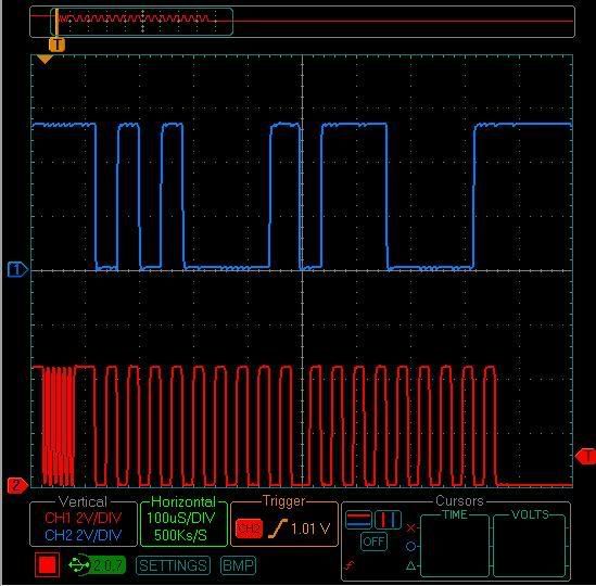
Hi. I just got the scope captures and here they are now. For these scope captures, we used putcI2C() instead of putsI2C(). PutcI2C sends one char at a time, while putsI2C sends a whole string at a time. However, putsI2C doesn't have line idle high at the end but putcI2C does. Below is the new scope capture.
Thanks.
Yu-Chen Shih
Posted: Tue Jun 12, 2007 3:31 pm
by Raquel
Do you still have pins 6 and 7 of the keypad connector jumped? We still do not see the display ACK'ing the address. With pins 6 and 7 jumped, the display puts the slave address to 0x50.
Did you by any chance change this slave address before?